JFTY image analysis system V2.0
General image analysis software
JFTY general image analysis software is the backbone software of JFTY image analysis system. It is the basis of other professional analysis and measurement software. It combines the latest image processing analysis technology, network technology, software technology and emerging optoelectronic products, and adopts Intel's image processing engine. The modular frame design, with rich processing, measurement functions and easy-to-operate interface, is very suitable for research and trial, and can be widely used in machinery, metallurgy, petroleum, chemical, geology, automotive, electric power, biology, medicine and other fields.
Universal image analysis software features, including
Image Acquisition
Image preprocessing
Target extraction
Target screening
Precise printing
Measurement of particle geometry parameters
Manual line length, angle, fold line
Analytical output of particle data
In a general image analysis system, an optical image can be photographed, processed, and analyzed for the geometry of the target object on the image, and individual particles or a batch of particles can be determined. And the measurement data is sent to the MS Excel spreadsheet software.
The system installation includes the installation and debugging of the hardware and the installation and debugging of the software. The installation and debugging of the hardness tester can refer to the respective instruction manuals according to the different hardness tester models. We mainly introduce the installation of the digital image part.
The installation steps generally follow the method of first peripheral and then host, first hardware and software.
Before installation, check whether the items are complete. Refer to the “shipping list†to check whether the items are complete.
Refer to the respective instruction manual.
The installation of the interface will vary depending on the hardness tester (generally, the corresponding connection hole is reserved at the position along the vertical direction of the hardness tester objective lens, the interface is screwed or inserted into the connection hole), and the interface is adjusted and stabilized. The synchronization with the observation under the eyepiece is the main requirement, and the synchronization includes the synchronization of the center of the field of view and the synchronization of the imaging focal plane.
Mainly refers to the installation of analog camera or digital camera, whether it is analog camera or digital camera, it is generally consistent with the camera-optical system interface, through the C interface thread connection, if it is an analog camera, you need a video The cable is connected to the analog camera and the digital acquisition device. If it is a digital camera, it depends on the digital interface to connect different digital interfaces, such as USB interface, or 1394 interface. The digital camera mounts the camera's driver or acquisition demo software on the computing host. The installation of these driver software is described in the installation of the software system.
Generally refers to the image capture card or digital capture card. First open the computer case, install the capture card on the PCI slot, and screw on.
The dongle is a guarantee for the normal use of the software. The dongle usually has a parallel port or a USB dog. Plug the dongle into the parallel port (LPT) or USB port on the back of the chassis. The normal use of the dongle requires the installation of the appropriate driver on the computing host, the installation of the driver, we put it in the installation of the software system.
For the installation of computers and output devices, refer to the operating instructions of the general computer. It is recommended to select a brand computer so that convenient technical support can be obtained. The installation of the computer is based on the complete installation of the drivers for all relevant equipment.
We introduce the installation of the hardware driver of the image analysis system in the installation of the software, including the installation of the dongle driver, the installation of the digital camera or the image capture card driver, and the installation of the image analysis software.
After the computer connection is installed, start the system and you will be prompted to find new hardware. Click Cancel.
Then insert the installation disk of JFTY image analysis system, it will start automatically, the above interface appears, click directly, install the dongle driver, the following interface appears.
If you have installed the dongle driver, you will be prompted. According to the type of dongle (USB dog/parallel dog) that comes with the installation disk, select the USB dog driver or the parallel port dog driver, and then click, after the installation is complete, you will be prompted and click.
After the installation is successful, you can see the dongle device in the device manager, as shown in the figure above, this is a USB dog device.
The driver installation of the dongle can also be run directly from the installation disk, the installation disk: \DogDriver\MicroDogInstdrv.exe.
Click "Next"
Click "Yes (Y)"
Click "Next"
Enter the user name and company name. In particular, you need to pay attention to anyone who chooses to use this machine/only. This will involve normal use when multiple users such as Win2000 or XP log in.
Here, you can select the directory where the JFTY metallographic image analysis system is located, which by default is C:\ImageSystem.
Enter the name of the program folder, which will appear in Start - Programs.
After confirming it is correct, click "Next"
Start copying and installation of files
Complete the installation of the software and a shortcut appears on the desktop.
At this point, the software and driver parts are installed.
Menu function
-------------[ ( N ) New Image Ctrl+N ]
Reopen a blank image processing window.
-------------[ ( C ) Open image... ]
In the current image processing window, open an existing image.
The following image formats are supported: bitmap file, JPG format, PNG format, PICT format, TIFF format, TARGA format, Windows Metafile format, Windows Enhanced Metafile format, pcx format, Protable greymap format
-------------[ ( E ) Open image in new window ]
Open an existing image and create a new image processing window for this image.
-------------[ ( S ) Save image... ]
Save the original image in the current image processing window.
-------------[ ( A ) Save image... ]
Display current active image |
Save the original image in the current image processing window in another file name or other image format
-------------[ ( G ) Get images... ]
A picture is acquired from a still image capturing device such as a scanner, a digital camera, or a digital camera, and displayed in the current image processing window. The selection of the still image acquisition device is in C ) Selecting a still image device . The interface for obtaining images varies greatly depending on the device. The interface is determined by the device's own driver. Under normal circumstances, there will be a capture/photograph function, which is to acquire images from static devices to JFTY image analysis software.
-------------[ ( L ) Take images...
An image is taken from an external dynamic image acquisition device (camera), and the operation interface is slightly different depending on the selected device. The operation interface of the V3A/C20/C30 and other image acquisition cards is as follows:
Save the current image to the specified file |
Capture the current image and pass it to the current image processing window |
In this interface, you can adjust the brightness, contrast, saturation, chroma, hue, X offset, Y offset and other parameters of the image. Each adjustment value will be saved automatically. The next time you start the function, the last parameter will be used. Value.
The operation interface of the WDM image acquisition device such as MV2000 is as follows. The general functions on the interface are the same as the above figure, mainly in the "setting" function, different devices will have different interfaces.
The operation interface of MV200 digital camera is as follows
JFTY image analysis system can support multiple acquisition devices on one computer at the same time, such as an analog camera connected to the stereo microscope, two digital cameras corresponding to a micro hardness tester and a metallographic microscope, then can pass ( D ) Select a dynamic image device to select different types of devices. If there are multiple devices of the same type, you can select the corresponding camera by selecting the image source after selecting the dynamic image acquisition device.
-------------[ C ] Select a still image device... ]
If a scanner, digital camera, digital camera, etc. are installed, you can see the static image acquisition device installed or connected in this interface, and select the device, then the device is used when obtaining the image .
-------------[ ( D ) Select a dynamic image device ]
In the board type supported by the system, select the currently installed board.
MVPCI Serial capture cards—V3A image capture card
OK serials capture cards—C20/C30 image capture card
DAHENG serials capture cards—CG300 image capture card
DCA (SDK) Serials Digital Camera - DCA2000 Digital Camera
DCA (WDM) Serials Digital Camera—DCA330 digital camera or other WDM device such as VT210
If the selected device type is incorrect, an image device initialization error will be prompted when the image is taken . In this case, first check if the type of the dynamic image device matches.
-------------[ ( P ) Precise magnification printing... ]
Print images at the specified magnification
The position of the picture in the preview box and the label text can be dragged by mouse
Number of pictures: There are 1-12 pictures available, and up to 12 fixed images can be printed on one piece of paper. The software will automatically typeset according to your choice.
Precisely printed button function introduction:
1. Print button: Issues a print command to the printer to print the current document.
2. Save as Word Document button: Save the current document as a Word document.
3. "Printer Settings" button: Set printer parameters.
4. "Back" button: Exits the fixed-width printing.
To change the print magnification of an image, double-click the image to make the appropriate selection in the pop-up dialog box.
You can click on “Pictureâ€, select the corresponding sample image that has been stored, then select “Organic Name†to find the corresponding objective image when using the objective lens, select or input “Print magnification†to determine the magnification when outputting. If the magnification is large, After the image is enlarged as a whole, beyond the paper size, the system automatically cuts the appropriate area at the center.
The normal use of the precise function needs to be performed after the system is calibrated.
-------------[ Exit ( X ) ]
Exit JFTY Universal Image Processing Analysis System
-------------[ ( T ) Toolbar ]
Whether to display the toolbar, tick to indicate
-------------[ ( S ) Status Bar ]
Whether to display the status bar, tick to indicate
-------------[ ( I ) Image Tools ]
Decide whether to display the image tool, tick the display
-------------[ ( O ) Results Window ]
Decide whether to display the result window, tick to indicate
-------------[ ( W ) Guide window ]
Decide whether to display the boot window, tick to indicate display
-------------[ ( C ) shows the original image ]
In the image processing window, only the original image of the current image is displayed, and the superimposed display of the binarized object, the automatic measurement object, and the manual measurement object is removed.
-------------[ ( B ) shows the binarization target ]
Display the superimposed display of the binarized target in the image processing window. In general, there is only one object with the red flag, the second object with the green flag, the third object with the blue flag, and the fourth object with the yellow flag. And so on, you can mark up to 16 objects at the same time.
-------------[ ( M ) Display manual measurement object ]
Display manual measurement objects such as points, lines, angles, polylines, closed areas, rulers, etc. in the image processing window
-------------[ ( R ) shows the object of automatic measurement ]
The object of automatic measurement is displayed in the image processing window, that is, it is marked with an edge line or a filled color block on the particles of the automatic measurement object.
-------------[ ( G ) Display measurement area ]
Display the measurement area in the image processing window
-------------[ ( E ) Display annotations ]
Display labels on images in the image processing window
-------------[ ( U ) superimposed ruler ]
Superimpose the ruler on the image in the image processing window
-------------[ ( H ) Horizontal direction histogram ]
After image binarization, the number of projections of the effective object in the horizontal direction is displayed. It can be used to observe the regularity of image tissue distribution, such as the change of decarburization layer/carburizing layer structure.
-------------[ ( V ) Vertical direction histogram ]
After image binarization, the number of projections of the effective object in the vertical direction is displayed. It can be used to observe the regularity of image tissue distribution, such as the change of decarburization layer/carburizing layer structure.
-------------[ ( F ) Image Filtering... ]
Image filtering mainly performs filtering processing on color/grayscale images. According to different filter kernels, it can filter out noise and extract edges.
FIG image filter box
The system has preset 15 filtering kernels, which can be selected by the operator. The left image shows a part of the current processing window, and the right image shows the processing effect. If you select a certain method, click “Applyâ€, then the current image processing window The content changes, you can continue to choose other processing methods, the operator can also customize the processing kernel, there can be 5X5 and 3X3.
-------------[ ( M ) Morphological operations... ]
Figure morphological operations dialog
It can be expanded, corroded, expanded, corroded, and expanded after being selected.
Both expansion and corrosion can be carried out along the four neighborhoods of the eight neighborhoods at a horizontal angle of 45 degrees and 135 degrees vertically.
The expansion can bond small cracks or voids, and corrosion can stick to the target.
The noise is broken or the isolated small noise is removed.
First etch and then expand (open operation) to remove noise
Corrosion after first expansion (closed operation) can fill the cavity
-------------[ ( F )FFT transform... ]
Perform FFT transformation on the image in the current image processing window
-------------[ ( A ) Arithmetic and logical self-operation... ]
FIG arithmetic and logic operation box itself
-------------[ ( D ) Arithmetic and logical participation in the operation... ]
It refers to the addition/subtraction between two images, which can be used to find the difference between different conditions in the same sample.
FIG arithmetic and logic operation box participation
-------------[ ( B ) Image binarization... ]
What is image binarization
In the above figure, for example, image binarization divides the graphite object of the field of view by threshold. In order to facilitate the computer calculation to distinguish the object to be calculated from the background, and also for the operator to intuitively control the object to be measured, the separated object is marked with a color, and the image binarization is mainly based on the image. The difference in brightness or color difference between the objects in the object, so that the brightness area or the color area (threshold value) of the divided measurement object and the background can be adjusted to adjust the object area to be measured, and the operator observes the change of the coloring area.
Adjusting the threshold range can be done by dragging the two lines in the histogram distribution range in the binarization dialog box, or directly adjusting the value range under the histogram distribution range, or directly selecting on the image by clicking.
Upper and lower threshold range |
Select directly on the image |
You can directly adjust the split threshold by dragging and dropping |
Whether to display brightness and all color components |
Whether to superimpose the color block mark on the object |
FIG target binarized box
If the image extraction is not complete or too much, you can re-extract the threshold by adjusting the size of the threshold until it meets the requirements.
Here we focus on the "mouse point pick" operation method, select the appropriate point to take the frame size, the system has 1X1, 3X3, 5X5, 7X7, 9X9, 15X15 several options, mainly representing the size range selected on the image each time. , and then click "mouse click", the binarization dialog disappears, the mouse is like a small viewfinder, and the framing box on the upper left of the mouse is placed on the object to be measured, together with the object with similar brightness and color. And put the color, if you can, click the right mouse button to exit, if the brightness or color span of the object is large, click on the different colors, you can right click to exit, select the range to add, and then enter the "mouse point" , the brightness/color range of each click is accumulated until the relevant measurement objects are colored.
By creating a new target/delete target, you can add/delete object categories and extract multiple phases at the same time.
-------------[ ( A ) Partition binarization ]
Partition binarization divides an image area into several small areas. Each small area calculates its own segmentation threshold. The partition binarization can be uneven for the field of view illumination, or the object to be measured is small. Within the field of view, the amount of information is small.
-------------[ ( T ) Osteogenesis ]
The measurement object that has been colored is reduced to a bone/network structure with a line width of 1, and is often used for simulation such as grain size grain boundaries.
-------------[ ( C ) Remove twigs ]
Remove the already skeletonized line/network structure to the short branch.
-------------[ ( R ) Corrosion ]
The measurement object that has been colored is reduced according to its shape.
-------------[ ( D ) Expansion ]
The measurement object that has been colored is expanded according to its shape. Corrosion and expansion can be used together to achieve the purpose of separating the adhesion particles.
-------------[ ( F ) Target filtering... ]
For measurement objects that have been separated (colored) from the background according to the brightness/color, further separation can be performed according to the geometric characteristics of each measurement object itself, and the unnecessary objects are deleted, leaving the object to be measured close. For example, the graphite in the ductile iron can be separated from the pearlite having a similar color brightness according to the degree of spheroidization. Or the size of the particles removes stains generated during the preparation process.
Figure goal Filter dialog
You can choose to filter the target in the current field of view by screening factors such as area, hole area, perimeter, length and short diameter.
Parameter Description
Enter the maximum value: remove the target with the filter factor greater than the maximum value in the current field of view.
Enter the minimum value: remove the target with the filter factor less than the minimum value in the current field of view.
Enter the maximum value of the minimum value: remove the target between the maximum and minimum filter factors in the current field of view.
The maximum value, the minimum value can be input manually, or the calculation of the existing target can be performed by clicking the button on the right.
get.
-------------[ ( C ) Set the scaling factor... ]
FIG dialog system calibration
What is the scaling factor?
The scaling factor is the actual length value of one pixel in the field of view.
The scaling factor can be measured by measuring the external scale
Scaling coefficient = actual length of external scale / length of pixel
Length = pixel point length ╳ scaling factor when performing length measurement
The importance of the calibration factor
The scaling factor values ​​are involved in the calculations during software measurements. Its accuracy is directly related to the accuracy of the measurement results, so we must ensure the accuracy of the calibration coefficient when doing system calibration. Of course, the appropriate amount of error is inevitable and objective.
How to perform system calibration
System calibration can refer to the following steps
(1) Ingest the ruler image into the software and click the “Set Calibration Factor†menu to bring up the following window.
(2) Select the objective lens, unit, click the button, draw the line segment of indefinite length along the standard grid, and the following interface appears.
(3) Fill the length of the obtained ruler into the "actual length". In this example, the scale is 0.01 mm per square, and the length of the scale is 0.01 mm X 13 grid = 0.13 mm or 130 um.
(4) Click the button, the measurement coefficient is automatically calculated and displayed in the “Scale Factor†(you can also directly input the measurement coefficient). As shown below:
(5) Finally, click the button and the calibration factor will be saved as the measurement coefficient. The entire calibration process is completed.
(6) Exit.
pay attention
It is also necessary to set multiple scaling factors under different magnification conditions. These values ​​are different from each other because a scaling factor can only represent the length value of an image point at a certain magnification. Therefore, in the actual measurement, when the magnification changes, the calibration coefficient should be changed or rescaled accordingly, otherwise the calculated data will be inaccurate.
-------------[ ( P ) Setting measurement parameters... ]
Set measurement parameters dialog
Measuring frame processing:
Border particles are ignored: Incomplete targets in the measurement frame do not participate in the calculation.
Border particle cut: Incomplete target cutoff calculation in the measurement frame.
The border grain contains: a complete calculation of the incomplete target in the measurement frame.
Measurement parameter selection
Area: The actual area of ​​the measurement object, in square micrometers, without the hole portion of the particle
Area (with holes): The actual area of ​​the measurement object containing the hole, in square micrometers
Hole area: The area of ​​the hole inside the measurement object, in square micrometers
Perimeter: The circumference of the measurement object, in microns
Roundness: the degree of roundness of the measurement object
Vertical projection: the projection length of the measurement object in the Y direction
Horizontal projection: measuring the projection length of the object in the X direction
Area equivalent circle diameter: diameter of the same circle as the area of ​​the measurement object
Perimeter equivalent circle diameter: diameter of the same circle as the circumference of the measuring object
Center of gravity X coordinate: X coordinate of the center of gravity of the measurement object
Center of gravity Y coordinate: the Y coordinate of the center of gravity of the measurement object
Long path: measure the length between the two points farthest from the edge of the object
Short path: the length between two points that are the shortest distance from the edge of the long diameter
Feret diameter: area of ​​the measuring object / length of the particle
Extension rate: aspect ratio short diameter
Long diameter inclination: the angle between the long diameter and the X axis
Spheroidization rate: The degree to which the measurement object is similar to the circle.
Long diameter/short diameter ratio: long/short diameter of the measuring object
Number of holes: The number of holes inside the measurement object.
-------------[ ( A ) Area percentage... ]
Figure percentage area of the dialog box
Automatically measures the area percentage of the target and the actual image in the current field of view.
-------------[ ( M ) Manual measurement ]
Figure manual measurement dialog
In the current field of view, the line length and angle can be manually measured on the target image. Note: In order to ensure the accuracy of the actual measurement data, it is necessary to complete the system calibration before manual measurement.
-------------[ ( U ) Measurement and calculation... ]
Graph measurement and calculation dialog
After selecting this menu, a dialog box will pop up, and the parameters of all targets in the current field of view will be displayed in the parameter display column (including: area, hole area, perimeter, roundness, vertical projection, horizontal projection, equivalent). Area circle diameter), and you can filter and classify the target or save the processed results to Excel, or output an analysis report.
The mouse clicks on the measurement data to view the corresponding target in the image, and the target of the mouse click on the image can also display the corresponding measurement data.
-------------[ ( G ) Data Analysis... ]
---------------- Transfer to Excel :
All data currently measured can be transferred to Excel for further analysis. It can be saved on the computer as an Execl format file.
---------------- Current image granularity analysis report
Output Excel's granular analysis report, you can enter the report range of the particle distribution, and the number of partitions.
-------------[ Cascade ( C ) ]
Cascading all windows
-------------[ tiling ( T ) ]
Tile all windows
-------------[ Arrange icons ( A ) ]
Arrange all icons
-------------[ Help topic ( H ) ]
Online online help
-------------[ About the image star... ( A ) ]
Software related information
Intermediates of Cladribine, Carvedilol, Lurasidone, olmesartan,
Risedronate Sodium, Atazanavir, Saxagliptin,
Dabigatran,Dapoxetine,Cefixime,Ceftaroline fosamil and etc.
In the short span of time, we have emerged as most promising
pharmaceutical intermediates manufacturers, chemical intermediates and
bulk drug intermediates suppliers. Our consistent supply, quality
products and dedication towards clients have opened up many
international avenues for our growth.
In addition, the company also can follow the customer's product needs custom synthesis services
MAIN API PRODUCTS USP/BP
|
PRODUCT NAME
|
CAS NUMBER
|
SPEVIFICATION
|
|
Azithromycin
|
117772-70-0
|
BEP
|
|
Cefpirome Sulphate sterile
|
84957-29-9
|
USP JP16
|
|
Ceftriaxone Sodium (Sterile)
|
104376-79-6
|
USP31
|
|
Cefotaxime
|
64485-93-4
|
USP30
|
|
Ciprofloxacin HCL
|
85721-33-1
|
USP/BP
|
|
Gentamicin sulphate
|
1405-41-0
|
BP
|
|
Levofloxacin
|
100986-85-4
|
USP27
|
|
Lincomycin Hydrochloride
|
859-18-7
|
EP6.0
|
|
Moxifloxacin Hydrochloride
|
186826-86-8
|
USP31
|
|
Tigecycline
|
220620-09-7
|
USP
|
|
Linezolid
|
165800-03-3
|
EP
|
|
Dexamethasone
|
50-02-2
|
USP/BP/EP
|
|
Methylprednisolone
|
83-43-2
|
USP/BP/EP
|
|
Dexketoprofen trometamol
|
156604-79-4
|
BP2008
|
|
Ibuprofen
|
15687-27-1
|
BP
|
|
Metamizol
|
68-89-3
|
DAB
|
|
Sulindac
|
38194-50-2
|
USP/BP/EP
|
|
Naproxcinod
|
163133-43-5
|
USP28
|
|
Tripelennamine Hydrochloride
|
154-69-8
|
USP28
|
|
Itraconazole
|
84625-61-6
|
USP/BP
|
|
Cytarabine
|
147-94-4
|
USP31
|
|
Leucovorin Calcium
|
1492-18-8
|
USP32
|
|
Valsartan
|
137862-53-4
|
USP30
|
|
Telmisartan
|
144701-48-4
|
USP31
|
|
Rosuvastatin Calcium
|
147098-20-2
|
USP/BP
|
|
Pitavastatin Calcium
|
147526-32-7
|
USP/BP
|
|
Fluvastatin
|
93957-54-1
|
USP31
|
|
Vinpocetine
|
42971-09-5
|
EP6.0
|
|
Atazanavir
|
198904-31-3
|
BP
|
|
Rosiglitazone
|
122320-73-4
|
USP30
|
|
Esomeprazole Magnesium
|
161973-10-0
|
USP/BP
|
|
Topiramate
|
97240-79-4
|
USP31
|
|
Fexofenadine HCl
|
153439-40-8
|
Inhouse
|
|
Bosentan
|
147536-97-8
|
Inhouse
|
|
D-Cysteine
|
921-01-7
|
Inhouse
|
|
D-Phenylalanine
|
673-06-3
|
Inhouse
|
|
Linagliptin
|
668270-12-0
|
Inhouse
|
|
Rivaroxaban
|
366789-02-8
|
USP
|
|
Saxagliptin
|
361442-04-8
|
USP
|
|
Vildagliptin
|
274901-16-5
|
USP
|
Major Pharmaceutical Intermediates
|
Items Descripation
|
Structure
|
Application
|
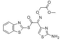
MICA ESTER
CAS No: 246035-38-1
Purity: ≥98%
|
|
For Cefixime
|
EHATA
CAS No: 64485-82-1
Purity: ≥98%
|

|
For Ceftazidine
|
2-Chloroadenine
CAS No: 1839-18-5
|

|
For Cladribine, Fludarabine et al
|
Bicyclo(2,2,1)Heptane-2,3-di-exo-carboximide
CAS No: 14805o-29-9
|

|
For Lurasidne
|
(R,R)-1,2-Bis(methanesulfonyloxy methyl)Cyclohexane
CAS No: 186204-35-3
|

|
For Lurasidone
|
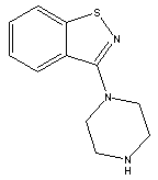
3-(Piperazin-1-yl)benzol[d] isothiazole
CAS No: 87691-87-0
|
|
For Lurasidone
|
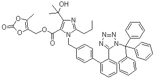
Trityl olmesartan
CAS No: 144690-92-6
Purity: ≥98%
|
|
For olmesartan
|
3-Acetyl Pyridine
CAS No: 350-03-8
|

|
For Risedronate Sodium
|
3-(AceticAcid)pyridine HCL
CAS No: 6419-36-9
|

|
For Risedronate Sodium
|
Risedronic Acid
CAS No: 105462-24-6
|

|
For Risedronate Sodium
|
3-Hydroxy-1-adamantyl-D-Glycine
CAS No: 709031-29-8
|

|
For Saxagliptin
|
(1s,3s,5s)-3-(aminocarbonyl)-2-azabicyclo(3,1,0) hexane-2-carboxylic acid tert-butyl ester
CAS No: 361440-67-7
|

|
For Saxagliptin
|
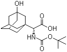
(S)-N-Boc-3- hydroxy-adamantylglycine
CAS No: 361442-00-4
|
|
For Saxagliptin
|
2-Azabicyclo[3.1.0] hexane-3-carbonitrile, (1s,3s,5s)-
CAS No: 866083-42-3
|

|
For Saxagliptin
|
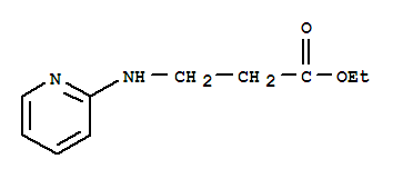
Ethyl 3-(pyridin-2-ylamino) propanoate
CAS No: 103041-38-9
|
|
For Dabigatran
|
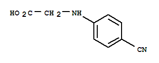
N-(4-Cyanophenyl) glycine
CAS No: 42288-26-6
|
|
For Dabigatran
|
4-methylamino-3-nitrobenzoic Acid
CAS No: 41263-74-5
|

|
For Dabigatran
|
S-3-Amino-3-phenylpropanoic acid ethyl ester HCL
CAS No: 167834-24-4
|

|
For Dapoxetine
|
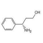
(S)-3-Amino-3-Phemylpropan -1-ol
CAS No: 82769-76-4
|
|
For Dapoxetine
|
(S)-3-Dimethylamino-3-Phemylpropanol
CAS No: 82769-75-3
|

|
For Dapoxetine
|
4-{4-[4-(hydroxydiphenylmethyl)-1-piperidinyl]-1-butynil}-α,α-dimethyl benzene acetic acid
CAS No: 832088-68-3
|
|
For Fexofenadine HCl
|
Methyl 2-(4-(4-chlorobutanoyl)phenyl)-2-methylpropanoate
CAS No:154477-54-0
|

|
For Fexofenadine HCl
|
5-Bromo-2-chlorophenyl)(4-ethoxyphenyl)methanone
CAS No 461432-22-4
|

|
For Dapagliflozin
|
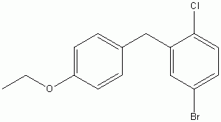
4-(5-Bromo-2-chlorobenzyl)phenyl ethyl ether
CAS No :461432-23-5
|
|
For Dapagliflozin
|
APIs & Intermediates
Mica Ester,Pharma Intermediates,Ciprofloxacin Hcl Uses,Active Pharmaceutical Ingredients
NINGBO VOICE BIOCHEMIC CO. LTD , https://www.pharma-voice.com


